Your Cart is Empty


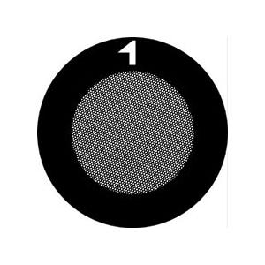
G600HSS
The Gilder grids are available in 50 to an unrivalled ultra fine 2000 mesh. The Gilder grids feature well defined grid bars, shiny (smooth) and matt side difference and are packaged in custom anti-static vials. They are made with precision electroplating technologies. An additional feature of the Gilder grids are the rim and center marks to aid in the orientation on the grid and identification of each side. Most Gilder grids have a rim mark and many grids also have center marks. Wide selection of grid styles to support virtually every application with standard diameter of 3.05mm. Available materials are Cu, Ni, Au, Mo and Cu/Pd. Thickness of Nickel grids is typically 35µm ±5µm.
Packaging:
Standard Cu, Ni or Cu/Pd, 100 grids/vial except special configurations which are listed accordingly with packaging of 25 or 50 grids/vial.
Thickness of Nickel grids is typically 35µm ±5µm.
Thickness of Mo grids is typically 25µm - 50µm.
Molybdenum is used principally in applications where its hardness, expansion coefficient, high temperature and corrosive resistance characteristics are considered important. Mo typical purity 99.9%, melting point 2617° C (4742.6°F).
Fine Bar: Pitch 42µm, Hole Width 37µm, Bar Width 5µm, Transmission 78%
Thick-Thin, hole size 30µm, bar 10/16µm, center-marked
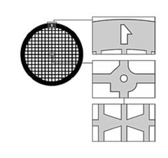
Standard Mesh Grids with marks:
An asymmetrical mark in the rim, shown top. Center mark for quadrant location or older style, “reverse arrow”, bottom.

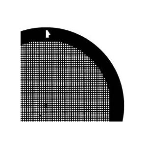
Fine Mesh Grids with marks:
An asymmetrical mark in the rim, shown top. Center mark divides grid into 6 areas, bottom.
Gilder Standard Square Mesh - overall thickness variation: G50: 25µm , ±5µm; G600TT: 6µm , ±2µm
| Rim Width: | 300-500µm |
| Thickness: | Square Mesh 6-25µm Hex 10-25µm Parallel Bar 12-27µm Slot 25-60µm Aperture 25-50µm |
| Diameter: | 3.05mm |
| Packaging: | 100 grids/vial for standard Cu, or Ni grids 50 grids/vial for Au 25 grids/vial for Mo 25/15/10 grids/vial for ultra fine mesh |
| Pitch: | Is 1"/mesh or 25.4mm/mesh Example 200 mesh pitch = 25.4/200 = 127µm |
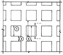
From the drawing above, the hole and bar widths are shown. Sometimes "pitch" is used in this terminology and it is the equivalent of hole width plus bar width.
| Material | Code |
| Copper | G or GC |
| Nickel | GN |
| Gold | GG /G-G, or G-AU |
| Copper/Palladium | G-CUPD |
| Molybdenum | G-M |
| Square Mesh |
Pitch µm |
Hole Width µm |
Bar Width µm |
% Trans- mission |
Mark | |
| Center | Rim | |||||
| G50 | 500 | 420 | 80 | 70 | - | - |
| G75 | 340 | 285 | 55 | 66 | • | • |
| G100 | 250 | 205 | 45 | 67 | • | • |
| G100HEX | 250 | 220 | 30 | 77 | - | - |
| G150 | 165 | 125 | 40 | 45 | • | • |
| G150HEX | 165 | 130 | 35 | 62 | - | • |
| G200 | 125 | 90 | 35 | 52 | • | • |
| G200HEX | 125 | 105 | 20 | 70 | - | - |
| G200HH | 125 | 113 | 12 | 82 | - | • |
| G200HS | 125 | 113 | 12 | 82 | - | • |
| G300 | 83 | 58 | 25 | 49 | • | • |
| G300HS | 83 | 73 | 10 | 77 | - | • |
| G300HEX | 83 | 58 | 25 | 49 | - | • |
| G300HH | 83 | 73 | 10 | 77 | - | • |
| G400 | 62 | 37 | 25 | 37 | • | • |
| G400HS | 62 | 54 | 8 | 76 | - | • |
| G400HEX | 62 | 37 | 25 | 36 | - | • |
| G400HH | 57 | 49 | 8 | 74 | • | • |
| G400P | 62 | 40 | 22 | 65 | - | • |
| G600TT | - | 30 | 10/16 | - | • | - |
| G600HH | 37 | 29 | 8 | 61 | • | • |
| G600HHS | 42 | 37 | 5 | 78 | - | • |
| G600HSS | 42 | 37 | 5 | 78 | - | • |
| G1000HS | 25 | 19 | 6 | 57 | - | • |
| G1000HH | 25 | 19 | 6 | 57 | - | • |
| G1500HS | 16.5 | 11.5 | 5 | 49 | - | • |
| G1500HH | 16.5 | 10 | 6 | 40 | - | • |
| G2000HS | 12.5 | 7.5 | 5 | 36 | - | • |
| G2000HA | 12.5 | 6.5 | 65 | 41 | - | • |